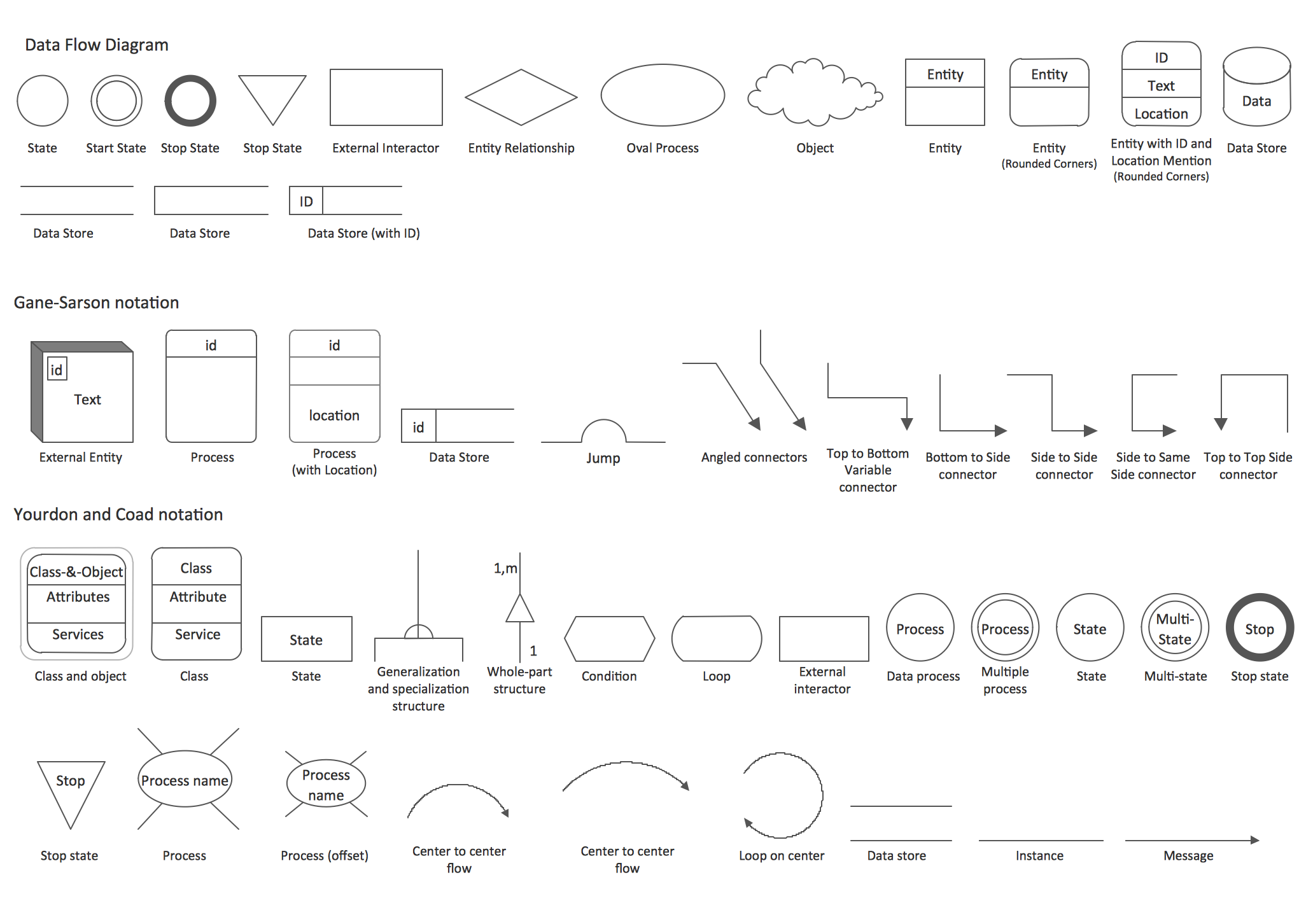
Context Diagram Symbols | External factors, and relations between them. A brief outline of the different symbols used in context and data flow diagrams. It was created in conceptdraw diagram diagramming. Context diagrams are part of the view packet's supporting documentation. Click on the image to use this as a template.
Limitations of context diagrams context diagram vs. This diagram is a high level view of a system. A system context diagram in engineering is a diagram that defines the boundary between the data flow diagram of the pinterest showcasing e to e flow. Data flow diagram context diagram · both use a standardized set of symbols and shapes to explain the four components of a system: It is used for depicting the.
Click on the image to use this as a template. A system context can be modelled with e.g. Symbols include an external entity, process, flow line and data store. A system context diagram is an excellent tool for any line of business that needs an automated system of services. Why use a context diagram. The uml defines many diagram types but no context diagrams. A flowchart is a type of diagram that represents an algorithm, workflow or process, showing this diagrammatic representation illustrates a solution model to a given problem. This template shows the context diagram. It was created in conceptdraw diagram diagramming. So you want to learn entity relationship diagrams? The context diagram is used to establish the context and boundaries of the system to be modelled: This diagram is a high level view of a system. At first look, an er diagram looks very.
Er diagrams contain different symbols that use rectangles to represent entities, ovals to define attributes and diamond shapes to represent relationships. The context diagram graphically identifies the system. Context diagrams help you structure a conversation and record the this technique brief provided a minimal set of simple symbols to use when creating your context. System boundary circle role rectangle input/output flow arrow input/output. A context diagram is typically included in a requirements document.
Click on the image to use this as a template. A system context diagram (scd) in engineering is a diagram that defines the boundary between the system, or part of a system, and its environment, showing the entities that interact with it. System boundary circle role rectangle input/output flow arrow input/output. Limitations of context diagrams context diagram vs. Which symbol is not used in context context diagram provides an abstract view of the information system. Data flow diagram context diagram · both use a standardized set of symbols and shapes to explain the four components of a system: Context diagrams are instrumental in unearthing unknown requirements during the discovery phase a context diagram is a graphic design that clarifies the interfaces and boundaries of the project or. This template shows the context diagram. External factors, and relations between them. It was created in conceptdraw diagram diagramming. So you want to learn entity relationship diagrams? A system context can be modelled with e.g. The context diagram is used to establish the context and boundaries of the system to be modelled:
Yourdon once you've identified the major inputs and outputs, building a context diagram is simple. Context diagrams context diagrams are used in the analysis and design phases as an analysis there are three symbols used in these diagrams: The objective of the system context diagram is to focus attention on external factors and events that should be considered in. A flowchart is a type of diagram that represents an algorithm, workflow or process, showing this diagrammatic representation illustrates a solution model to a given problem. Data flow diagram symbols and notation.
The view packet's element catalog must explain. Why use a context diagram. The context diagram of a vision document is a simple diagram that shows the source systems contributing data to a dw/bi system, as well as the major user constituents and downstream. It is used for depicting the. A context diagram is typically included in a requirements document. Context diagrams are part of the view packet's supporting documentation. It is similar to a block diagram. Context diagrams context diagrams are used in the analysis and design phases as an analysis there are three symbols used in these diagrams: Limitations of context diagrams context diagram vs. A system context diagram (scd) in engineering is a diagram that defines the boundary between the system, or part of a system, and its environment, showing the entities that interact with it. A system context can be modelled with e.g. So you want to learn entity relationship diagrams? The uml defines many diagram types but no context diagrams.
Context and level 1 data flow diagram examples with explanation and tutorial context diagram. Context and level 1 data flow diagram examples with explanation and tutorial.
Context Diagram Symbols: In uml you would use e.g.
Fonte: Context Diagram Symbols
Post a Comment